4. Alternating Current
Definitions
- Capacitance is the stored charge between 2 metal plates
- Dielectric is the insulated barrier separating 2 plates in a capacitor
- Fleming’s Left Hand Rule: When a current is passed through a coil in a magnetic field, a force acts on the coil to try and make it turn
- Fleming’s Right Hand Rule: If a conductor is moved through a magnetic field an electric current will be generated
- Amplitude is the height of a waveform
- Peak value of a waveform is the maximum positive or negative value
- Peak to peak value is the difference between the maximum positive and maximum negative value. It is normally twice the peak value.
- RMS (root mean square) is the equivalent D.C. current or voltage that would produce the same heating effect as the A.C. waveform
- Out of phase waveforms have the same frequency but start at different times
- In phase waveforms have the same frequency and start at the same time
- Capacitive reactance is a measure of a capacitor’s opposition to AC
- Inductive reactance is a measure of an inductor’s opposition to AC
- Resonant frequency is the frequency at which the inductive reactance is equal and opposite to capacitive reactance in a series tuned circuit
- Magnification / Q Factor is the ratio of the voltage across the inductor (or capacitor) to the supply voltage at resonance
- Bandwidth of a selectivity curve is the frequency range where the output is at least 0.707 of the maximum value
- Filter is a circuit that will pass some frequencies and reject others
Units of measurement
Faradsis a unit of capacitanceJoulesis the unit of work doneDegreesis the unit for phaseHenrysis the unit for inductance
Formula
E = ½(CV²)whereEis energy stored in capacitorQ = CVwhereQis quantity of electricity,Cis capacitance,Vis voltageT = RCwhereTis time constant,Cis capacitance,Ris resistanceC = C₁ + C₂ + C₃whereCis total capacitance in parallel1/C = 1/C₁ + 1/C₂ + 1/C₃whereCis total capacitance in seriesRMS √2 = RMS x 1.414 = V (peak)whereRMSis the RMS / DC equivalent voltage,1.414is root 2,V (peak)is the maximum peak voltageω = 2πfwhereωis angular rotationXc = 1/ωC = 1/(2πfC)whereXcis capacitive reactive,ωis angular rotationXc = V / IwhereXcis the reactive capacitance,Vis the DC Voltage,Iis the ACXL = ωL = 2πfLwhereXLis inductive reactanceZ = √(R² + XL²)whereZis impedance,Ris resistance,XLis inductive reactance for an RL series circuitZ = √(R² + Xc²)whereZis impedance,Ris resistance,Xcis capacitive reactance for an RC series circuit- For an RLC series circuit:
V² = (VL - Vc)² + Vr²whereVis total voltage,VLis voltage across inductor,Vcis voltage across capacitor,Vris voltage across resistorV ∝ ZZ² = (XL - Xc)² + R²whereZis total impedance,XLis inductive reactance,Xcis capacitive reactance,Ris resistance of the resistor
-
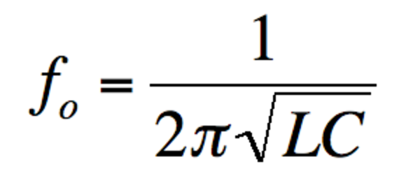
or
2πf = 1/√(LC)wherefois resonant frequency,Lis inductance,Cis capacitance Z = L/CRwhereZis dynamic impedance in a parallel tuned circuit at resonance,Lis inductance of the inductor,Cis capacitance of the capacitor,Ris resistance of the resistorQ = fo / (f2 – f1)whereQis the ratio,fois resonant frequency,f1is lower bound,f2is upper bound
Circuit diagrams
-
Capacitor-resistor in series

-
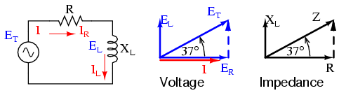
Inductor-resistor in series
- RLC (resistor-inductor-capacitor) circuits:
-
series circuit
-
parallel circuit
-
-
Parallel tuned circuit

Graphs
-
Leading and lagging

- Vector diagram
- angular rotation always goes anti-clockwise starting from 3 o’clock
-
Capacitor current-voltage phasor diagram
-
Inductor current-voltage phasor diagram

-
Phasor diagram comparison

-
Capacitive reactance
- Impedance
-
Capacitor-resistor in series circuit

-
Inductor-resistor in series circuit
-
-
Total voltage
Vsin RLC series circuit
-
Total impedance
Zin RLC series circuit
-
Total current
Isin RLC parallel circuit
-
Resonant frequency
- Tuned circuit resonant frequency
-
series circuit
-
parallel circuit
-
-
Bandwidth in a parallel tuned circuit

-
response graphs

Image credit: Electronic tutorial
Notes
Capacitance
- 2 metals are connected by battery
- Plate “B” is now negatively charged and repels so strongly that the current ceases
- The plates have a very small capacitance for the storage of electricity
- very important to have insulation (dielectric) between the plates that will stand up to the voltage that is to be used
Capacitance of a capacitor is:
∝area of the plates1/∝distance between the 2 plates∝permittivity of the dielectric between the plates
| Material | Permittivity |
|---|---|
| Air | 1 |
| Dry paper | 2.5 |
| Glass | 5 |
| Mica | 7 |
Construction of capacitors
- Paper capacitors
- “sandwich” of strips of foil and wax impregnated paper
- 2 foil forms the plates
- waxed paper is the dielectric
- Mica capacitor
- alternate layers of thin metal sheet
- thin layers of mica as dielectric
- Silvered mica
- Silver is sprayed on the sheets of mica to form the plates
- advantages:
- possible to make these capacitors very accurately
- value of the capacitance changes very little with wide temperature changes - E.g. suitable for the tuned circuits in oscillators - Ceramic capacitors - small pieces of ceramic that have a coating of silver on each side - E.g. suitable for de-coupling - disadvantages
- large capacitance variations with changes of temperature
- should not be used for tuned circuits - Electrolytic Capacitors - two aluminum foil strips - interleaved with an absorbent paper strip and wound very tightly into a cylinder - one capacitor plate is one of the foil strips and the other plate is the electrolyte - the oxide acting as the insulating dielectric - !! very important to ensure that electrolytic capacitors are connected right way round in any circuit - Variable capacitors (tuning capacitors) - one set of fixed plates and one set of moving plates - dielectric is usually air - When the plates are rotated they overlap, and hence the capacitance, changes
Alternating Current
- Generator
- has a coil that continues to rotate in the same direction
- produces electricity that flows in one direction for half a revolution and reverses in the next half cycle
- current and voltage are in sine-wave
Capacitance
- When a voltage is applied to a capacitor the initial charge current is high at a time when the voltage is small
- In a capacitive circuit:
- current leads the voltage by 90°
- voltage lags the current by 90°
Inductance
- In an inductor, voltage leads the current by 90°
RLC Circuit
| Series | Parallel | |
|---|---|---|
| Voltage across each component | calculate | same |
| Current across each component | same | calculate |
| R (resistor) | resistance in phase with voltage | resistance in phase with voltage |
| response curve resonant frequency | at minimum resistance | at maximum resistance |
| resonant frequency circuit | acceptor circuit | rejector circuit |
Tuned circuits are used in oscillators and radio receivers. They can be used to select one frequency when many are present.
Selectivity
- A high Q circuit has good selectivity of frequencies
- A low Q circuit has poor selectivity of frequencies
- Parallel tuned circuit would typically have a
Qof50
Filters
