5. Power Supply Units
Definitions
- Half wave rectification will allow current flow through the load during the positive half cycles
- Full wave rectification will allow current flow through the load during both positive and negative cycles
- Diode bridge configuration circuit allows for full wave rectification of an input AC souce
- Voltage Regulators are circuits that help to maintain a constant voltage output
Diagrams
Power Supply Unit
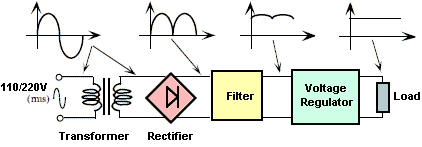
Image credit: Electronics Area
Circuit diagrams
-
Half-wave rectification
Image credit: Electronics Tutorial
-
Full-wave rectification

Image credit: Electronics Tutorial
Image credit: Play hookey
-
Voltage regulators

Image credit: Fairchild Semiconductor
Graphs
-
Zener diode graph
Image credit: Electronics Tutorial
Notes
Most modern Amateur Radio equipment operates:
13.8 V DClow voltage supply20 Ahigh current
Power supply from:
- outdoors: car battery
- indoors: convert the 230 Volt AC “mains” to 12 Volt DC
| Power Supply Unit | Components | Description |
|---|---|---|
| Mains | 230V AC | |
| Transformer | step-down Transformer | (1) capable of handling the required power (2) primary winding of the transformer usually has a few “taps” so that various mains voltages can be used |
| Rectifier | 1 or more diodes | (1) very simple circuit will produce a great deal of hum at the supply frequency 50 Hz (2) A full wave rectifier circuit gives an output that contains hum at twice the supply frequency 100 Hz |
| Smoothing (filtering) | large capacitor | In order to further reduce the hum an inductor and a another large capacitor are added |
| Stabilizer (Voltage regulator) | zener diode | (1) If a zener diode is reversed biased there is a critical voltage at which the current flow increases dramatically (2) Beyond this “knee” in the characteristic, a very small change in voltage will result in a large change in the current passed |
| Output | load |