11. Interference
Definitions
- Interference may be due to faults and/or deficiencies in either the transmitter or in the receiver or both
- Blocking happens if the receiver is situated close to a transmitter when the transmitter Is operating
- Key clicks are generally undesired “clicks” or “thumps” generated by a CW transmitter as the key is put down or let up.
- Chirp is a signal in which the frequency increases (up-chirp) or decreases (down-chirp) with time.
- A braid-breaker is a filter that prevents television interference
- Ferrite bead or ferrite choke is a passive electric component that suppresses high frequency noise in electronic circuits.
Diagrams
Circuit diagrams
-
Key click filter

-
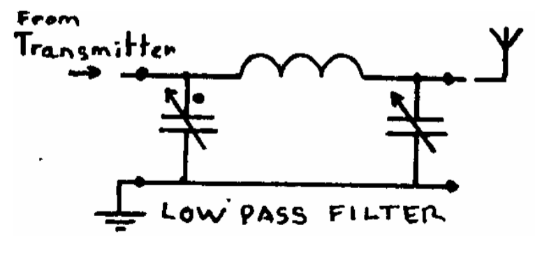
PI-network circuit
-
Braid breaker

Notes
Receiver problems
- Blocking
- if the receiver is situated close to a transmitter
- receiver is blocked when the transmitter is operating
- receiver, although tuned to another frequency, becomes overloaded and it will no longer ‘hear’ the wanted station
- Second channel interference
- Most receivers are of the superheterodyne type and reply on mixing
- for a given Local Oscillator frequency and Intermediate Frequency there will two frequencies
- frequency of the unwanted station will be 2X the IF away from the wanted frequency
- RF stage of the receiver should be designed to reject the ‘second channel’
- Local Oscillator Harmonics
- If the LO in the receiver generates harmonics these will cause unwanted mixing products
- unwanted stations could be received
- Detection
- If the receiver or Hi-Fi is not well screened then the RF from a nearby transmitter may enter and be detected by any non-linearity in the audio stages
- IF Breakthrough
- If a receiver has an Intermediate Frequency in an Amateur Band then any transmission on that frequency might be received where ever the receiver is tuned.
- very important that the high gain IF stages of a receiver are well screened
Resolution
- ensure that the receiver does not get an extremely strong signal from the Amateur Transmitter
- TV / VHF receivers: ensure that the outer of the coax cable does riot act as an aerial for the amateur transmissions
- A filter (braid breaker) can be connected in the coax near to the TV or hi-fi
- screen is then no longer connected directly to the receiver
- loss at UHF TV and VHF hi-fi frequencies is very low
- This filter should be fitted about one Metre along the cable from the receiver
- Signals picked up on the outer of the cable can also be much reduced by winding it several times through a ferrite ring
Deficiencies
- Receiver deficiencies
- internally
- add inductance to the base circuit of a transistor
- passing the base connection through a small ferrite bead - externally
- A rejector circuit is a parallel tuned circuit and at its resonant frequency it is a high impedance. Therefore it is connected in series with the aerial wire
- The acceptor is a series tuned circuit and it will have a low impedance at resonance. It is therefore connected across the aerial and earth connection to ‘”short circuit1” the unwanted frequency - Transmitter deficiencies - A Morse (CW) transmitter, although simple, is capable of producing clean harmonic free transmissions - Morse key is up: no output - Morse key is pressed: a full output until it is released and the output drops abruptly - sudden changes (arrowed) will generate clicks that are rich in harmonics - annoying clicks will be heard, not only on the transmitted frequency, but also on its harmonics - solution:
- wave shape must be rounded to remove those harmonic laden sharp corners
- a key click filter comprises of a coil, capacitor and a resistor wired into the Morse key
- coil prevents a sudden build up of current when the key is pressed
- decay of the current is prolonged by the capacitor and the resistor when the key is released
Types of Interferences
- Harmonic transmission
- all waveforms apart from sine waves contain harmonics
- important to ensure that any harmonics produced by a transmitter are not actually transmitted
- harmonics must not reach the aerial
- Harmonic reduction
- A PI-network is connected between the aerial socket of the transmitter and the aerial wire
- very effective in reducing harmonics:
- 4X better than a simple parallel tuned circuit for reducing the second harmonic
- 9X better than at the third harmonic - frequency multiplier stages of the transmitter should be carefully screened to ensure that no ‘unwanted’ frequencies escape - Fit a low pass filter in the transmitter output - important to have good earthing and de-couple all the power leads - Over modulation - must be avoided in an amplitude modulated transmitter - transmitter should be designed so that over modulation cannot occur - an indicator should be fitted to show when 100% modulation is being approached - Parasitic (or spurious) Oscillations - Certain stages of a transmitter may break out into self oscillation at a an apparently random frequency - Low Frequency
- Amplifiers may burst into oscillation that cannot be sustained
- Transistors that are used in Radio Frequency amplifiers usually have an unwanted, high gain at audio frequencies - Signal Frequency
- Amplifiers may oscillate at the frequency they are intended to amplify
- an avoided by ensuring adequate screening
- avoided with a change in the component layout - High Frequency
- usually at VHF
- Valve power amplifiers suffer from this problem
- resolved by adding a low value resistor or a small coil at the grid tag
- difficult to see which of the components have “unintentionally” formed a tuned circuit at VHF
- even a straight piece of wire has some inductance at VHF - Chirp - A Morse transmitter should be designed to maintain a constant frequency - If the Variable Frequency Oscillator (VFO) or crystal oscillator is not adequately buffered or the power supply adequately stabilized then the frequency may shift during the “key down” period
Unwanted frequencies
- All the unwanted products must be attenuated to ensure that they do not appear at the output to the aerial
- Ensure unwanted frequencies do not leak out
- Also possible that unwanted frequencies are being produced by non-linear devices outside the transmitter