12. Meters
Definitions
- Cathode Ray Oscilloscope / CRO / scope is a type of electronic test instrument that allows observation of constantly varying signal voltages, usually as a two-dimensional plot of one or more signals as a function of time
- Absorption wave meter is a simple electronic instrument used to measure the frequency of radio waves
- SWR / VSWR (voltage standing wave ratio) meter measures the standing wave ratio in a transmission line. The meter can be used to indicate the degree of mismatch between a transmission line and its load (usually a radio antenna), or evaluate the effectiveness of impedance matching efforts.
Diagrams
-
Modulation
Circuit diagrams
-
Absorption wave meter circuit 1
-
Absorption wave meter circuit 2

Formula
- Average DC of peak AC =
0.637* peak AC - Depth of modulation =
(A - B) / (A + B)whereAis maximum envelope height,Bis minimum envelope height
Notes
Different Types
- Moving coil meter
- Used for direct current / voltage only
- For AC the pointer will vibrate at 0
- AC at low frequency
- the current is rectified before it passes through the meter coil
- many meters use a metal oxide full wave bridge rectifier
- shunts & multipliers are then added to give various AC ranges
- AC at high frequency
- diode bridge will have too much self-capacitance
- can be reduced by using special low capacitance diodes
- better to use thermocouple meter, hot wire ammeter, oscilloscope
- Thermocouple
- a small voltage is generated when two different metals are joined together
- Voltage generated is proportional to the temperature at the joint
- Radio Frequency (RF) current to be measured is passed through a heater wire that is close to one junction
- Thermo-couple meter is slow to react but will indicate RMS values, whatever the waveform
- Hot wire ammeter
- RF current is passed through a wire that is suspended between two fixed points
- current warms up the wire and causes it to expand
- expansion is used to mechanically move the pointer of a meter
- wire is kept under tension by a little spring
- as it relies on the heating effect, will indicate RMS that is independent of frequency
- Cathode Ray Oscilloscope (CRO or “scope”)
- similar to thermionic valve
- In the CRT (cathode ray tube) the stream of electrons is focused (by focus anode) into a narrow beam that strikes a phosphor coated screen
- point on the screen “hit” by these electrons gives off light
- electric field is set up between the deflection plates
- plates:
- plates that deflect the beam vertically are called the “Y” plates
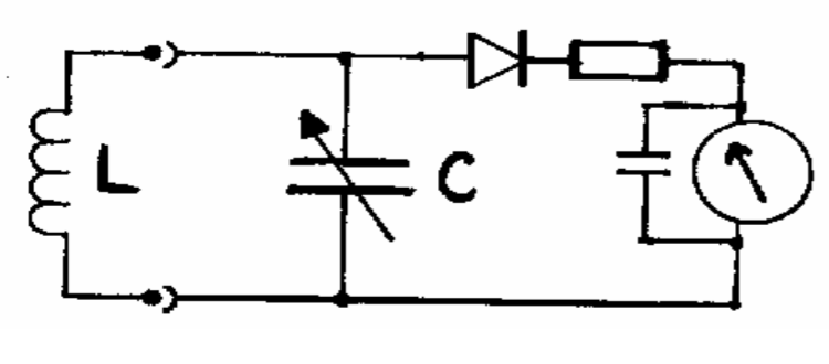
- plates that deflect the beam horizontally are called the “X” plates - Absorption wave meter circuit types - Circuit 1
- has the disadvantage that the tuned circuit (L & C) would have a low Q
- they are damped by the diode and meter circuit - Circuit 2
- overcomes this problem by having a second coil to couple the signal into the meter circuit
- coils act like a step down transformer and matches the high impedance L & C to the low impedance meter circuit
- supplied with several plug-in coils so that a wide range of frequencies are covered
- dial, fitted to the tuning capacitor, may have all the ranges marked directly or, simply, a
0to100logging scale - frequency meter of this simple type would often cover1MHzto100MHzin several ranges - absorption wavemeter gives a low accuracy measurement of frequency - it is adequate to ensure that a transmitter is selecting the correct oscillator harmonic - often used when adjusting a transmitter by ensuring that the correct harmonic or mixing product, is selected at each stage - Digital Frequency Meter - the counter actually counts the number of cycles (of the frequency to be measured) that reach it during the time that the gate is open - not practical to make a 1Hz oscillator (to control the gate) - low frequency is obtained by a crystal oscillator running at a much higher frequency, say1MHz-1MHzis then passed though a series of “divide by ten circuits” - gate could be open for10sec,1sec,0.1sec- only as accurate as crystal controlled oscillator - very important to ensure its frequency does not drift
- part of the circuit is usually enclosed in a temperature controlled compartment - DFM could be used for checking:
- Oscillator (VFO or crystal)
- Frequency output of each stage
- Frequency of the final output of a transmitter, but not if the transmission is SSB or deeply modulated AM - A frequency counter should not be used to check that a transmitter is using the correct multiplication factor - should first be done with a simple absorption wavemeter
Modulation
Depth of Modulation
- Modulate the transmitter with a sine wave
- Connect the transmitter to a suitable dummy load and connect the CRO Y plates across it
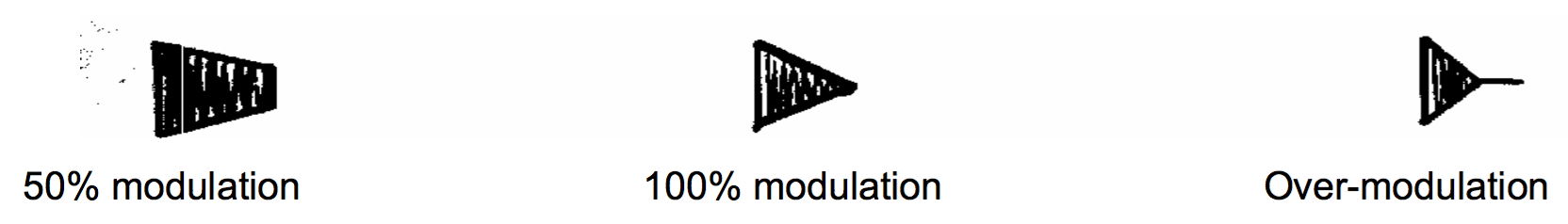
Method 1: modulation depth
- apply the CRO’s own timebase to its X plates
- modulation envelope will be displayed
- shows a high frequency carrier wave whose amplitude follows the shape of the modulating signal
- maximum (A) and the minimum (B) dimensions are them measured
- CRO display does not need to be calibrated as it is just the ratio of A and B that is used in the depth of modulation calculation
Method 2: modulation depth
- time-base is disconnected from the X plates of the CRO
- replaced by a proportion of the audio modulating signal
- This will give a trapezium display on the CRO screen
Dummy loads
- When setting up (tuning up) or testing a transmitter, it is important that minimum interference is caused to other stations
- most of this work should be done with the transmitter not connected to the aerial
- Aerial must be disconnected and power must be suitably absorbed
- dummy load must be of an impedance to match the transmitter output usually
50Ω/75Ωfor handling~100W - construct a
50Ωdummy load from10 X 500Ωin parallel, with each resistor rated at10W - you can use a lower rated resistor if they are immersed in oil